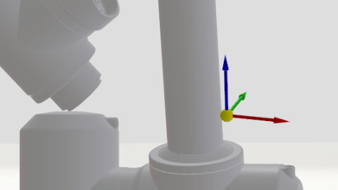
Goodmorning, we are using our robot model AWTube_phaseA.glb with our mech_parameters.xml in our MCX project started from "Antrophomorphic" template project but with kdl solver.
Our Actual Tool Pose is wrong, but the issue is that on an older project called "Robofox_noFSOE" the same configuration works. Do you change anything related to the kinematics in the newest version of .bin ?
<?xml version="1.0" ?>
<robot name="AWTube_phaseA" numberDoFs="6" type="kdl_nrjl">
<basepose>
<position x ="0.0" y="0.0" z="0.0"></position>
<orientation a="0" b="0" c="0"></orientation>
</basepose>
<segment number="1">
<tippose>
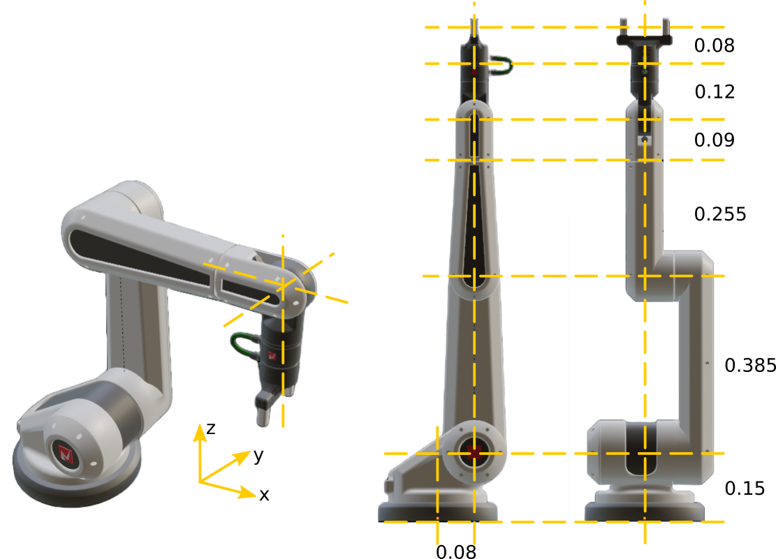
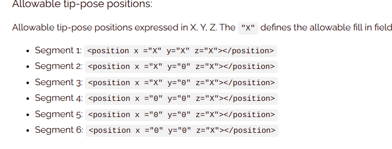
<position x ="0" y="0" z="0.117"></position>
</tippose>
<jointaxis>
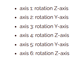
rot_z
</jointaxis>
<mass>
0
</mass>
<inertia>
<Ixx> 0 </Ixx>
<Ixy> 0 </Ixy>
<Ixz> 0 </Ixz>
<Iyx> 0 </Iyx>
<Iyy> 0 </Iyy>
<Iyz> 0 </Iyz>
<Izx> 0 </Izx>
<Izy> 0 </Izy>
<Izz> 0 </Izz>
</inertia>
<cog>
<position x ="0" y="0" z="0"> </position>
</cog>
</segment>
<segment number="2">
<tippose>
<position x ="0" y="0" z="0.725"></position>
</tippose>
<jointaxis>
rot_y
</jointaxis>
<mass>
0
</mass>
<inertia>
<Ixx> 0 </Ixx>
<Ixy> 0 </Ixy>
<Ixz> 0 </Ixz>
<Iyx> 0 </Iyx>
<Iyy> 0 </Iyy>
<Iyz> 0 </Iyz>
<Izx> 0 </Izx>
<Izy> 0 </Izy>
<Izz> 0 </Izz>
</inertia>
<cog>
<position x ="0" y="0" z="0"> </position>
</cog>
</segment>
<segment number="3">
<tippose>
<position x ="0" y="0" z="0"></position>
</tippose>
<jointaxis>
rot_y
</jointaxis>
<mass>
0
</mass>
<inertia>
<Ixx> 0 </Ixx>
<Ixy> 0 </Ixy>
<Ixz> 0 </Ixz>
<Iyx> 0 </Iyx>
<Iyy> 0 </Iyy>
<Iyz> 0 </Iyz>
<Izx> 0 </Izx>
<Izy> 0 </Izy>
<Izz> 0 </Izz>
</inertia>
<cog>
<position x ="0" y="0" z="0"> </position>
</cog>
</segment>
<segment number="4">
<tippose>
<position x ="0.675" y="0" z="0"></position>
</tippose>
<jointaxis>
rot_x
</jointaxis>
<mass>
0
</mass>
<inertia>
<Ixx> 0 </Ixx>
<Ixy> 0 </Ixy>
<Ixz> 0 </Ixz>
<Iyx> 0 </Iyx>
<Iyy> 0 </Iyy>
<Iyz> 0 </Iyz>
<Izx> 0 </Izx>
<Izy> 0 </Izy>
<Izz> 0 </Izz>
</inertia>
<cog>
<position x ="0" y="0" z="0"> </position>
</cog>
</segment>
<segment number="5">
<tippose>
<position x ="0" y="0" z="-0.3681"></position>
</tippose>
<jointaxis>
rot_y
</jointaxis>
<mass>
0
</mass>
<inertia>
<Ixx> 0 </Ixx>
<Ixy> 0 </Ixy>
<Ixz> 0 </Ixz>
<Iyx> 0 </Iyx>
<Iyy> 0 </Iyy>
<Iyz> 0 </Iyz>
<Izx> 0 </Izx>
<Izy> 0 </Izy>
<Izz> 0 </Izz>
</inertia>
<cog>
<position x ="0" y="0" z="0"> </position>
</cog>
</segment>
<segment number="6">
<tippose>
<position x ="0" y="0" z="0"></position>
</tippose>
<jointaxis>
rot_z
</jointaxis>
<mass>
0
</mass>
<inertia>
<Ixx> 0 </Ixx>
<Ixy> 0 </Ixy>
<Ixz> 0 </Ixz>
<Iyx> 0 </Iyx>
<Iyy> 0 </Iyy>
<Iyz> 0 </Iyz>
<Izx> 0 </Izx>
<Izy> 0 </Izy>
<Izz> 0 </Izz>
</inertia>
<cog>
<position x ="0" y="0" z="0"> </position>
</cog>
</segment>
<tool-offset name="tool1">
<position x ="0.0" y="0" z="0">
</position>
<orientation a="0" b="0" c="0">
</orientation>
</tool-offset>
</robot>
@Alex_Corrado